

In short. LV generator switchgear is the 415 V assembly that connects one or more diesel generators to the loads: generator breakers, bus, incomer and feeder breakers, interlocks and metering. It is specified by continuous current, prospective fault current, bus and breaker ratings, form of separation and the room it sits in. At generator ratings above about 500 kVA the current climbs past 700 A and busbar, breaker and heat decisions start to dominate the design.
Where the switchgear sits in a generator system
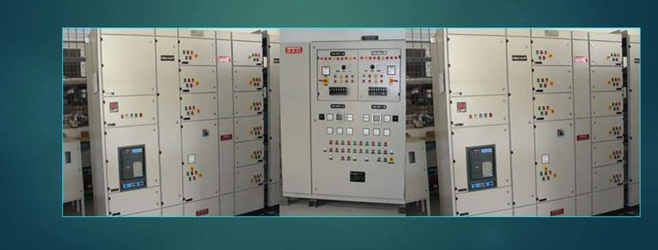
Between the alternator terminals and the first distribution board there is always a switching and protection point, even on a single set with an AMF panel. As the installation grows, that point becomes a proper switchboard: a generator incomer breaker for each set, a common generator bus, a coupler or changeover to the utility section, and outgoing feeders to the essential boards. In a paralleled plant the synchronising panel and the generator breakers are usually one assembly, with the master controls mounted in or beside it. Where the loads are small and the transfer is simple, an automatic transfer switch may do the whole job and no separate switchboard is needed.
Current first: why kVA becomes amperes
Everything about LV switchgear scales with current, and the current from a 415 V generator is large.
I = S / (√3 × V)
Here I is the line current in amperes, S the apparent power in VA and V the line-to-line voltage in volts. Worked example (illustrative): a 1,000 kVA set at 415 V delivers 1,000,000 / (1.732 × 415), about 1,391 A at full load. A 2,000 kVA set delivers about 2,780 A. These figures decide the busbar section, the breaker frame, the number of parallel cables per phase and the heat the enclosure must reject. Two sets of 1,000 kVA on a common bus mean a bus and coupler rated for at least 2,800 A, and typically the next standard frame above that to leave margin for ambient temperature and future load.
The design variables that must be fixed
| Variable | What fixes it | Typical consequence of getting it wrong |
|---|---|---|
| Rated continuous current | Sum of sets that can run together, at site ambient | Busbar overheating, nuisance trips at high load |
| Short-circuit withstand (Icw, Ipk) | Fault study including generator, utility and motor contribution | Bus or breaker damage during a fault |
| Breaker type and frame | Current, fault duty, need for draw-out maintenance | Breaker cannot interrupt or cannot be isolated safely |
| Form of separation | Maintenance philosophy, who will work on it live | Whole board shut down for one feeder job |
| Ingress protection and ventilation | Room, dust, monsoon humidity, heat load | Condensation, tracking, derated breakers |
| Control supply | DC battery or UPS for closing and tripping coils | Breakers that cannot trip when the bus is dead |
Fault duty on generator supply is different
A utility transformer delivers a fault current that stays roughly constant until it is cleared. A diesel generator delivers a high current for the first few cycles, governed by its subtransient reactance, which then decays over the following tens of cycles as the field responds. For a typical industrial alternator the first-cycle contribution is around six to ten times rated current and the sustained value, with a PMG or short-circuit maintenance excitation, settles near three times rated current. The peak withstand of the switchgear must cover the first-cycle value, which for a 2,000 kVA plant can approach 30 kA peak before motor contribution is added. The breaker’s interrupting capacity and the bus short-time withstand are then checked against the utility fault level as well, since the same board usually sees both sources. Our generator fault current guide covers the decay curve in more detail. Adding a generator to an existing utility-fed board can also raise the fault level at the point where the generator breaker lands, and a board that was adequate yesterday may be underrated today.
Breakers, busbars and heat
Choosing the breaker
Below roughly 630 A a moulded-case breaker with an electronic trip unit is the usual generator breaker. Above that, and wherever draw-out isolation or motorised operation for synchronising is needed, an air circuit breaker is the right choice. The trip unit must carry a long-time setting matched to the alternator thermal capability, a short-time setting that rides through motor starting and transformer inrush, and an instantaneous setting that still catches a close-in fault once the generator current has decayed. Selection criteria are set out in ACB, MCCB and MCB selection.
Busbars and temperature rise
Busbar section is set by temperature rise under the assembly standard, not by a current-density rule. In a Hyderabad plant room that reaches 45 °C in May the permitted rise above ambient is consumed quickly, and copper that would be fine in a 35 °C test room runs hot. Ventilation louvres, forced cooling of the enclosure, or a larger bar section are the normal responses, and the switchboard thermal engineering page works through the calculation.
Maintainability and future expansion
A switchboard lives twenty years or more and will be worked on many times. Specify it so that one feeder can be isolated, tested and have its breaker racked out while the rest of the board stays live; that means Form 3b or Form 4 separation for a board feeding critical loads, and draw-out breakers on the generator incomers. Leave at least one spare generator incomer cubicle and the bus rating to match if a further set is at all likely; retrofitting a cubicle onto a live bus is expensive and disruptive. Provide test terminal blocks on the CT and VT circuits so that secondary injection testing can be done without disturbing wiring, and label every breaker with its source and its interlock partner.
Related photographs and videos
Common mistakes
- Rating the bus for the connected load rather than for the generators that can run together. When all sets are online for a test the bus runs above its rating.
- Taking the fault duty from the utility study alone. The generator contribution at the generator bus is ignored and the peak withstand is exceeded.
- Feeding breaker closing and tripping coils from the bus they control. With the bus dead, nothing can be closed, and during a fault the trip supply collapses with the voltage.
- Specifying Form 1 separation for a board that feeds a hospital or data hall. Every feeder modification becomes a full shutdown.
What to send us
Send the single-line diagram, the kVA and voltage of each generator, the utility transformer rating and impedance if known, the list of outgoing feeders with their currents, and photographs of the room where the board will stand, including the cable entry. If you are adding a generator to an existing board, send its nameplate, the bus rating and a photograph of the incomer breaker label. Use the application engineering enquiry page.
Questions engineers ask
At what generator size do I need an ACB rather than an MCCB?
Current, not kVA, decides. MCCBs are available up to 1,600 A and beyond, but above about 630 A, and wherever the breaker must be racked out for maintenance or motor-operated for synchronising, an ACB is the practical choice. For a 500 kVA set at 415 V, around 700 A, most designers move to an ACB.
Does adding a generator change the fault level of my existing switchboard?
At the generator bus, yes. The generator adds its own subtransient contribution on top of whatever the utility supplies when the two are paralleled, even momentarily during a closed-transition transfer. The board’s peak and short-time withstand must be checked against the combined value, not the utility figure alone.
Why do generator breakers need a separate DC control supply?
Because the breaker must close onto a dead bus and must trip during a fault that drags the bus voltage down. A 110 V or 24 V DC battery system, or a small UPS, keeps closing and tripping coils alive regardless of what the AC bus is doing, and its battery health should be tested as part of switchgear maintenance.
What ingress protection should a generator switchboard have indoors?
IP42 is common for a clean, ventilated room; IP54 is appropriate where dust or monsoon humidity enters. Higher sealing reduces cooling, so an IP54 board often needs a larger enclosure or forced ventilation to hold the busbar temperature rise within limits.
Technical content reviewed by Srinivas Reddy, Managing Partner, Reddy Generators. Last updated 19 October 2026.