

In short. A generator that starts but cannot transfer still leaves the building dark. ATS and switchgear parts, including the transfer controller, motor operators, shunt trips, undervoltage releases, auxiliary contacts, interlocks and sensing fuses, are identified by the switchgear maker, frame, coil voltage and the transfer philosophy, never by generator kVA. Any repair is proved by a complete mains-fail and mains-return test, not by one relay energising.
Power continuity does not end at the generator
An automatic standby system is a sequence. The transfer controller senses that the DISCOM supply has failed or gone outside limits, waits a short confirmation delay, signals the generator to start, checks that generator voltage and frequency are acceptable, opens the mains device, closes the generator device through an interlock, and later reverses the process when the mains return, with a cool-down run before the engine stops. Each step depends on hardware that sits in the panel rather than on the engine: sensing circuits, timers, relays, motorised mechanisms and the auxiliary contacts that tell the controller what actually happened. The principles of the switch itself are described on automatic transfer switches, and the panel that commonly houses them on AMF panels.
The parts, their jobs and what identifies them
| Part | Function in the sequence | Identification needed |
|---|---|---|
| ATS or AMF controller | Senses sources, decides, commands start and transfer | Exact model, hardware revision, firmware, saved configuration |
| Changeover switch or contactor pair | Carries load from one source or the other | Maker, frame, rated current, utilisation category, coil voltage |
| Motor operator | Opens and closes a moulded-case or air circuit breaker remotely | Breaker maker and frame, operator model, control voltage |
| Shunt trip | Opens a breaker on a command or protection signal | Breaker frame and accessory slot, coil voltage AC or DC |
| Undervoltage release | Opens the breaker when its control supply collapses | Frame, voltage, time-delay type if fitted |
| Auxiliary and alarm contacts | Report open, closed or tripped state to the controller | Frame, number and type of contacts, normally open or closed |
| Mechanical or electrical interlock | Prevents both sources closing together | Maker and frame pair, mounting arrangement |
| Sensing fuses, MCBs and control relays | Feed voltage sensing and control power | Rating, base type, coil voltage |
A request for “a shunt trip for a 1600 A breaker” is not yet a specification. The maker, the frame series, the accessory slot and the coil voltage all decide whether the part fits and works.
Diagnosing transfer failures by symptom
No transfer when the mains fail
Confirm first that the controller saw the failure. A blown sensing fuse on one phase can make the controller see the supply as healthy, or the reverse, depending on how it measures. Then check whether the start signal reached the generator, whether the generator voltage and frequency passed the acceptance limits, and whether the close command produced movement. A controller command does not prove that the breaker moved; the auxiliary contact feedback does.
No retransfer when the mains return
Retransfer timers of several minutes are normal and deliberate, so wait them out first. After that, look at mains sensing, the mains-close coil or motor operator, and any interlock that has not reset. A stuck undervoltage release on the mains breaker is a common culprit after a long outage.
Breaker will not close, or closes and trips at once
Check the spring charge on stored-energy breakers, the closing coil supply, the undervoltage release voltage and the interlock state. A breaker that trips immediately on closing may be doing its job because a downstream fault exists, so investigate the load side before forcing it.
Interlocks and synchronising checks are not obstacles
Open-transition changeovers rely on mechanical and electrical interlocks so that the generator can never be connected to the DISCOM network or to a dead mains bus that is about to be re-energised. Closed-transition and paralleling schemes rely on a synchronism-check function that allows closure only when voltage magnitude, frequency and phase angle are aligned within set limits. Defeating either to make the system transfer can backfeed the utility line, endanger linemen, or close two sources out of phase and put severe torque and current through the engine, coupling and alternator. Replacement parts must preserve the original interlocking philosophy. If closure is refused during synchronising, the cause is in the governor, the AVR or the sensing, which is where our synchronising and switchgear service starts.
Heat, wear and the evidence a failed part leaves
Switchgear in generator rooms in Hyderabad sees heat, dust and monsoon humidity. Loose busbar joints and lugs heat up under load, discolour, and eventually fail. A discoloured terminal is not cosmetic; it marks a high-resistance joint that must be cleaned, re-torqued to the maker’s figure and, where damaged, replaced. Contactors used for changeover wear their contacts with every operation, faster when switching motor loads, and their coils fail when control voltage is too low or too high. Any device that has interrupted a heavy fault should be inspected before return to service even if it still operates mechanically, because contact erosion and arc damage are hidden inside. Thermal imaging during a load test is a useful way to find hot joints before they fail.
Testing after any replacement
Bench checks prove a part. Only an integrated test proves the system. After work on ATS or switchgear components, the following sequence should be run and recorded.
- Control power present and correct at every coil and the controller.
- Voltage sensing on all phases of both sources, with correct phase rotation.
- Manual operation of each device, then electrical open and close.
- Interlock test: attempt to close the second source while the first is closed, and confirm it is blocked.
- Simulated mains failure by opening the incoming supply, with start, transfer time and voltage at the load recorded.
- Mains return, retransfer timer, retransfer and cool-down.
- Alarm and status feedback to the controller and any remote monitoring.
The acceptance question is whether the complete system delivers power to the load when the normal supply fails and returns it cleanly when the supply comes back. Our ATS service records each step. Used breakers and controllers need particular care over condition and settings, as set out in our used and refurbished parts policy. Device-level guidance is on breakers, contactors and relays.
Related photographs and videos
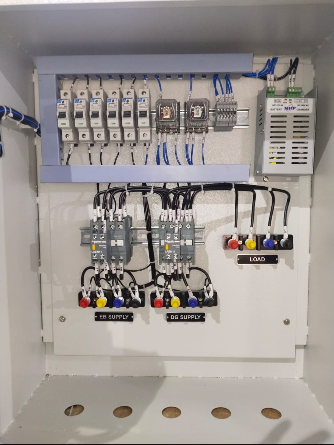
Common mistakes
- Bypassing an interlock to restore supply in a hurry; the generator backfeeds the mains or two sources close together and equipment or people are harmed.
- Ordering a breaker accessory by current rating alone; the shunt trip or auxiliary contact does not fit the frame and the panel stays down.
- Copying controller settings from another site with the same model; transfer delays and voltage limits suit the other site, not yours.
- Declaring the repair finished when one relay energises; the first real outage shows that retransfer or feedback still fails.
What to send us
Send photographs of the switchgear and breaker nameplates, the failed component with its label, and the panel wiring diagram if available. Tell us the generator rating, whether the system is a single ATS, generator-to-generator transfer or synchronising, the coil and control voltage, and exactly which step of the sequence fails. Send a spare parts enquiry.
Questions engineers ask
Why does the ATS wait before transferring to the generator?
A short delay, usually a few seconds, avoids starting the set for momentary dips and auto-reclose events on the DISCOM network. The generator also needs time to reach stable voltage and frequency before load is applied.
Can a contactor changeover replace a breaker-based ATS?
Contactor changeovers are common on smaller sets, but they have no inherent short-circuit protection and must be rated for the switching duty and backed by suitable protective devices. The decision depends on fault level, load type and the protection scheme.
What is an undervoltage release and why does my breaker keep opening?
It is a coil that holds the breaker closed only while its supply is healthy. If that supply is taken from a source that dips, the breaker opens. Check that the release voltage and supply point match the design.
How often should an ATS be tested on load?
A monthly off-load start test is common, with an on-load transfer test at least every few months and after any maintenance. The load test is what reveals sticking mechanisms and sensing faults.
Technical content reviewed by Srinivas Reddy, Managing Partner, Reddy Generators. Last updated 19 October 2026.