
The Generator Must Ultimately Interface With the Plant’s Real Distribution Architecture.
Industrial facilities may distribute power through:
PCC
Power Control Centres.
Related photographs and videos
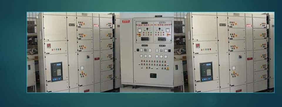
MCC
Motor Control Centres.
The generator must support the electrical behaviour downstream.
WHY MCCs MATTER
MCCs may contain:
- motors
- starters
- soft starters
- VFDs
- contactors
- protection.
These loads can materially influence generator transient behaviour.
RESTORATION STRATEGY
After transfer to generator power, should all motor feeders re-energise immediately?
Often the better question is:
Which motors should return first?
PCC INTERFACE
Generator integration may affect:
- breaker coordination
- bus loading
- source interlocking
- load shedding
- metering.
Plant power continuity is determined at the distribution board as much as at the generator.
Engineering intent
PCC & MCC Integration should be evaluated as part of the complete power system rather than as an isolated catalogue item. Operating duty, connected load, interfaces, protection, controls, installation conditions, testing requirements and lifecycle consequences determine whether the arrangement is appropriate.
Engineering considerations
A numerical relay can offer dozens of protection functions. That does not mean every function should be enabled.
Selection and design considerations
rated voltage • current • fault withstand • bus arrangement • protection • segregation • form of separation • ingress protection • internal arc considerations • operating environment. A PCC commonly performs major power reception and distribution functions. transformer incomers • DG incomers • bus couplers • high-capacity outgoing feeders • APFC connections • major distribution feeders. An MCC is organised primarily around motor/control feeders and associated industrial loads. motor breakers/fuses • contactors • overload/motor protection • starters • VFD feeders • control circuits • PLC interfaces. utility transformer • DG • multiple DGs • UPS output • BESS/PCS • alternate utility source. voltage • frequency • phase • neutral • earthing • rating • fault contribution • operating mode. motors • process equipment • HVAC • UPS • lighting • APFC • critical systems • non-critical systems. kW • kVA • current • PF • starting/transient behaviour • criticality.
Integration and protection considerations
UPS sizing • DG load management • selective shedding • maintenance • resilience. Do not distribute all loads indiscriminately from one undifferentiated bus. But load shedding and restoration must be controlled. The switchboard architecture should make the hierarchy visible. When available generation is insufficient for all loads, controlled shedding can prioritise: life/safety or process-critical loads → essential loads → discretionary loads Do not rely solely on manual emergency switching where automatic response is required. After source recovery, reconnecting all loads simultaneously can create a severe demand step. DOL starters • star-delta starters • soft starters • VFDs • process auxiliaries. Do not design the MCC as a row of identical cubicles.
Testing, commissioning and verification
Study the electrical system—not only the utility bill. The utility meter commonly evaluates conditions at the applicable point of supply/PCC. But local buses can have different reactive-power characteristics. Placing compensation closer to reactive loads can reduce upstream reactive current through parts of the distribution network. A central APFC bank can simplify control and maintenance. But reactive current still flows through downstream feeders between the loads and central compensation point. An intermediate strategy can compensate a group of loads at an MCC or process bus. But capacitor sizing and switching must avoid undesirable: At light load, this can influence facility PF. Therefore a plant’s PF is not determined by process motors alone.
Operating and lifecycle considerations
A long motor cable can materially reduce contribution at the upstream fault location. For an MCC bus fault, upstream source current flows toward the fault. At the same time, connected running motors can also feed the fault. For a main-switchboard bus fault, motors connected through several downstream MCCs can contribute back through their feeders toward the main bus. This can increase the main-bus initial fault duty. This direction reversal is an important conceptual point. A feeder breaker can therefore experience fault current from more than the upstream source depending on: The study should establish the actual current through each breaker—not merely total bus fault current. Ifault,total = Iutility + Itransformer / source + IDG + Iₘₒₜₒᵣ + Iᵢₙᵥₑᵣₜₑᵣ
Decision and application considerations
lug selection • number of parallel conductors • phase arrangement • bending radius • mechanical support • tightening/torque procedure. A correctly rated breaker cannot compensate for a poor termination. When multiple conductors operate in parallel, current sharing depends on appropriate: a small increase in joint resistance at high current can produce substantial local heat. Therefore joint preparation, fastening and verification are critical. hot joints • overloaded feeders • phase imbalance • deteriorating contacts. current • losses • enclosure • ventilation • ambient • internal equipment arrangement. Do not assume a universal allowable temperature-rise figure without the applicable assembly/component basis. busbars • breakers • contactors • VFDs • soft starters • control transformers • power supplies • reactors. A VFD-heavy MCC can have very different thermal requirements from a contactor-only MCC of similar feeder count.
Direct answer
The Generator Must Ultimately Interface With the Plant’s Real Distribution Architecture. PCC Power Control Centres.
The practical decision for PCC & MCC Integration should be based on verified load, equipment, interface and site information. Where equipment-specific data, regulatory applicability or a project study is required, this guidance does not replace that verification.