
POWER CONTINUITY DOES NOT END WHEN THE GENERATOR STARTS.
THE POWER STILL HAS TO BE TRANSFERRED, SWITCHED, PROTECTED AND DELIVERED TO THE LOAD.
An automatic standby system can be understood as:
If a generator starts correctly but the transfer or switchgear system cannot perform its intended function, the facility can still lose power.
Related photographs and videos
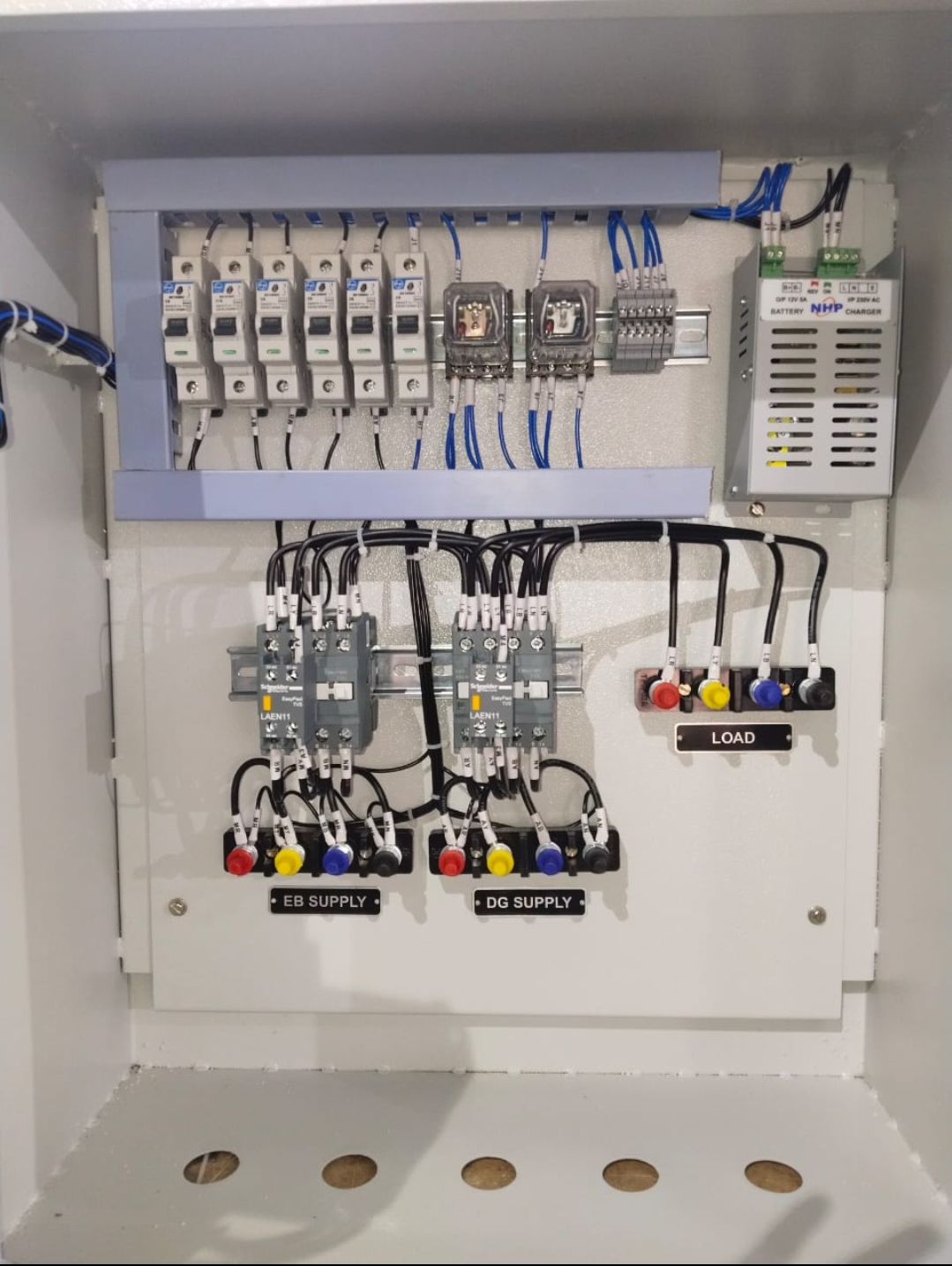
Do not identify a switchgear component merely from generator kVA.
Potential component families include, subject to verified support:
Breakers, Contactors & Relays will provide the dedicated Breakers, Contactors & Relays specialist page.
3. ATS Is a System—not Merely a Switch
→ utility-failure decision → generator start command → generator availability verification → transfer permission → mechanical/electrical interlocking → load transfer → source monitoring → utility restoration → retransfer → generator cooldown/stop.
The ATS needs credible information about source condition.
A failed sensing circuit can create an apparently intelligent but incorrect transfer decision.
→ exact model → hardware revision where available → firmware/configuration where relevant → front/rear photographs → connector details → switchgear identity → application.
A controller with the same display size is not automatically equivalent.
Do not copy settings from another installation simply because the controller model matches.
Transfer equipment must prevent inappropriate source connection according to the system architecture.
A replacement component must preserve the intended interlocking philosophy.
Do not bypass an interlock merely to make the system transfer.
A controller command does not prove breaker movement.
→ mechanism operates → breaker closes → auxiliary contact changes → controller receives confirmation.
Small auxiliary contacts can carry important status information.
Incorrect contact arrangement can cause major control-sequence problems.
A shunt-trip accessory can form part of remote/protection opening logic.
“Shunt trip for 1600 A breaker” is not yet a complete specification.
Where fitted, an undervoltage release can influence whether a breaker remains closed under the intended control-power condition.
Motorised breaker mechanisms may form part of automatic transfer or synchronising switchgear.
The correct breaker does not guarantee the correct motor operator.
Where contactors form part of transfer/control architecture, verify:
The attached protection guide makes an important point: generator protection selection is determined by configuration and consequences—not merely machine rating.
The protection guide demonstrates that CT ratio, saturation and matching can materially influence generator-protection performance.
Replacing a relay with technically suitable hardware does not establish correct protection.
The guide explicitly warns that its typical settings are only starting points and that actual settings depend heavily on the application.
Where generators are paralleled, breaker closure may depend on acceptable alignment of:
ATS & Switchgear Parts should therefore cross-link strongly to Synchronising & Switchgear Service.
19. Never Bypass Synchronism Protection to Force Closure
If a breaker will not close during synchronising:
Do not defeat synchronism-check logic merely to complete the connection.
Incorrect synchronisation can subject the generator and system to severe electrical and mechanical stress.
20. Switchgear Failure Can Exist Outside the Generator
ATS → breaker → control power → relay → interlock → cable → switchgear.
Where justified, inspection and thermal assessment can help identify abnormal heating.
Do not treat a discoloured component as merely cosmetic.
A component involved in significant electrical fault duty should not automatically be returned to service because it still moves mechanically.
The failure event can affect more than the visibly damaged item.
Investigate duty, coil supply, switching, current and mechanical operation.
Determine whether the breaker is defective—or correctly protecting the system.
REPLACE THE FAILED COMPONENT—AND REMOVE THE FAILURE MECHANISM.
For protection/control equipment, configuration status matters in addition to physical condition.
Used breakers, controllers and protection components require particularly careful condition disclosure.
Do not market an unknown used breaker as equivalent to a verified new component.
Upgrade & Replacement Planning provides the broader upgrade/replacement decision framework.
A switchgear modification without documentation creates future diagnostic risk.
→ control power → sensing → manual operation → breaker/switch operation → interlocks → automatic start request → source acceptance → transfer → retransfer → alarms → protection → feedback → documentation.
Do not declare success because one replacement relay energises.
For critical standby installations, the strongest acceptance question is:
Does the complete system deliver power when the normal source fails?
→ generator start → generator available → ATS decision → transfer → load supported → utility returns → retransfer → cooldown → standby restored.
ATS Controller Transfer Mechanism Breaker Accessory Motor Operator Shunt Trip Undervoltage Release Auxiliary Contact Contactor Protection Relay CT Meter Control Relay Other / Unknown
Generator rating Operating mode Single generator / multiple generator ATS / synchronising / utility parallel
Manufacturer Model Part Number Coil/control voltage Photographs
No Transfer No Retransfer Breaker Won’t Close Breaker Won’t Open False Trip No Start Command Controller Failure Interlock Problem Burnt Component Obsolete Part Unknown
→ monitored by ATS → ATS requests generator start → controller validates source → transfer mechanism/breaker changes supply → switchgear protects/distributes power → auxiliary contacts confirm status → critical load receives supply.
ATS and switchgear component selection must account for source availability, transfer logic and continuity at the load.
Provide component and nameplate photographs with the part number. Confirm OEM, genuine or compatible status and fitment against the exact part and machine before ordering.
For breakers, contactors and relays, confirm the equipment identity, electrical ratings, control interfaces and applicable compatibility evidence before ordering. Use the parts-identification enquiry to provide photographs, markings and the installation details needed for review.
Do not identify these components from generator kVA alone.
2. Breakers, Contactors and Relays Perform Different Functions
Designed to make/carry current and interrupt the circuit within its applicable ratings and protection/control architecture.
Designed primarily for electrically controlled switching appropriate to its utilisation duty.
Measures/interprets electrical conditions and decides whether protection action is required.
Provides control logic, isolation, multiplication or interfacing of signals.
“1600 A breaker” is not a complete technical specification.
4. Frame Size and Current Rating Are Different Concepts
Breakers can belong to a frame family supporting multiple current/trip configurations.
Never infer complete breaker capability from the headline ampere number alone.
A replacement breaker must be suitable for the electrical system’s prospective fault duty.
This means replacement selection cannot be based only on normal operating current.
The system fault level and applicable breaker ratings must be considered.
A breaker is part of a larger protection hierarchy.
→ sensing → protection decision → selected breaker trips → faulted section isolated → healthy system remains energised where architecture permits.
the source Generator Protection Application Guide explains that generator fault current can decay following a fault, which affects overcurrent-protection application.
This means generator protection should not simply copy a utility-fed distribution philosophy without engineering review.
The protection guide describes conventional phase-overcurrent protection as requiring coordination with external protection and discusses how motor starting, transformer energisation and external faults can influence relay behaviour.
A breaker may be doing exactly what the protection system commanded.
For applicable generators, differential protection can provide fast, selective internal-fault detection.
the source guide explains that an 87G element compares currents from CT sets and can remain substantially insensitive to normal load flow and external faults while responding to internal differential current, subject to CT considerations.
Breakers, Contactors & Relays should not imply every generator requires differential protection.
generator grounding arrangements can require different ground-fault protection approaches.
SAME GENERATOR + DIFFERENT GROUNDING = POTENTIALLY DIFFERENT PROTECTION REQUIREMENTS.
Replacement must preserve the intended protection function and coordination.
Do not assume that a physically compatible trip unit is functionally equivalent.
A shunt trip from a visually similar breaker series may not be suitable.
An incorrect accessory can prevent breaker closure or cause unintended opening.
Motor operators can support remote or automatic breaker operation.
Do not assume all motorised breakers use interchangeable operators.
Small feedback components can be crucial to ATS, synchronising and control logic.
the system should not automatically assume closure occurred.
→ breaker mechanism → breaker changes state → auxiliary contact changes → controller verifies.
Two otherwise similar contactors can use different coils.
Where two contactors or breakers control mutually exclusive sources, interlocking can be fundamental.
Do not bypass an interlock merely because the transfer system refuses to operate.
These categories are explicitly covered by the source Generator Protection Application Guide.
21. Relay Hardware Is Not the Protection Scheme
Installing a multifunction relay does not automatically establish protection.
→ wiring → configured elements → pickup values → time delays → logic → trip outputs → breaker → coordination.
Breakers, Contactors & Relays should therefore never treat CTs as generic current sensors.
Any CT work must preserve the intended measurement/protection architecture.
For paralleled generators, reverse power can indicate loss of prime-mover input while the generator remains connected to an energised system.
the source guide describes function 32 as sensing real power flowing into the generator under such conditions.
This demonstrates why protection-relay replacement can have direct mechanical consequences.
Loss-of-field protection can protect against excitation-related conditions that may cause reactive-power absorption, rotor heating and wider system effects.
The guide explains that negative-sequence current can induce double-frequency rotor currents and lead to heating.
Therefore protection should not be reduced to simple overcurrent alone where the application warrants broader protection.
Before paralleling, appropriate generator and system conditions must be established.
Do not bypass synchronism protection to force breaker closure.
This is one of Breakers, Contactors & Relays’s most important safety controls.
Therefore Breakers, Contactors & Relays must not publish universal relay settings.
If a breaker trips repeatedly, possible explanations include:
That can remove protection rather than solve the problem.
30. Never Upsize Protection to Stop Trips Without Engineering
A BREAKER THAT TRIPS MAY BE WARNING YOU ABOUT THE SYSTEM.
Direct answer
ATS and switchgear parts need to match the actual equipment, rating and operating arrangement. Provide the manufacturer, assembly model, device reference and available drawings.
The practical decision for ATS & Switchgear Parts should be based on verified load, equipment, interface and site information. Where equipment-specific data, regulatory applicability or a project study is required, this guidance does not replace that verification.
Related Reddy Generators pathways
- Generator Spare Parts
- Automatic Transfer Switches
- Find My Generator Part
- Parts Compatibility Verification
- Spare Parts Enquiry
- Generator Services
Protection-chain verification
A circuit breaker is the final interrupting element in a wider protection chain. Reliable fault clearing depends on measurement inputs, relay logic, control power, trip circuits, breaker mechanism, interruption time and selectivity operating together. Maintenance therefore needs to verify the complete detect → decide → trip → interrupt → isolate sequence, not merely the mechanical condition of the breaker.